Frequently Asked Questions
Find answers to common questions
About Navijin Technology
Can I get Navijin certificates?
What is Navijin Technology?
Where can I buy Navijin products?
Is Navijin a registered brand?
Do Navijin products have warranty and after-sales support?
Who owns Navijin and where is it headquartered?
How can I verify that a Navijin product or certificate is genuine?
Which industries use Navijin networks?
How can I become a Navijin partner or distributor?
Which countries does Navijin serve?
Does Navijin offer Wi-Fi 7 products?
Network Infrastructure
How to Initially Set up Navijin L2 Switches?
Initial Setup Guide for Navijin GE6010-24P2S-L2 Switch
1. Console Connection
To perform the initial configuration via console, follow these steps:
Equipment:
- Computer with a COM port or USB-to-RS232 adapter
- Console cable (RJ45 to DB9)
- Terminal access software (e.g., PuTTY, MobaXterm)
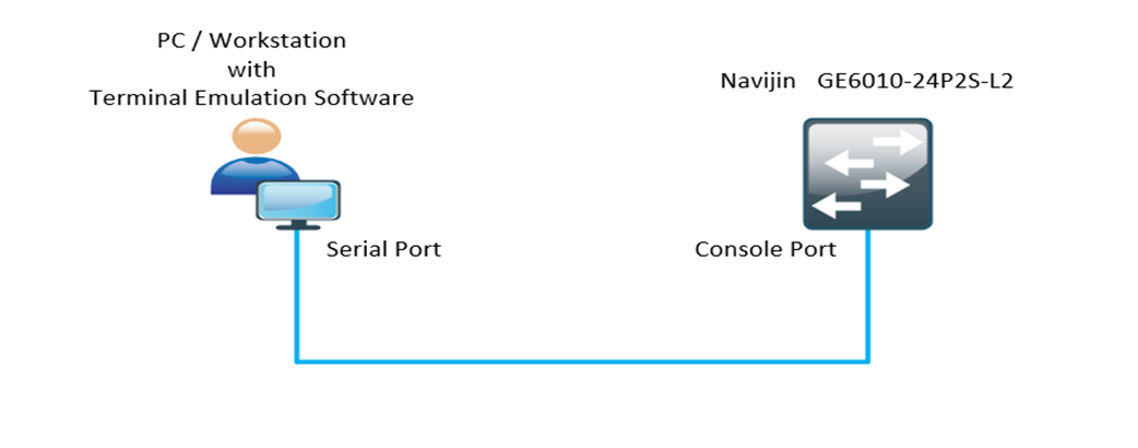
Steps:
- Connect the console cable to the switch's console port and to the computer's COM port.
- Open your terminal access software and configure the connection parameters:
- Baud rate: 115200
- Data bits: 8
- Parity: None
- Stop bits: 1
- Flow Control: Xon/Xoff
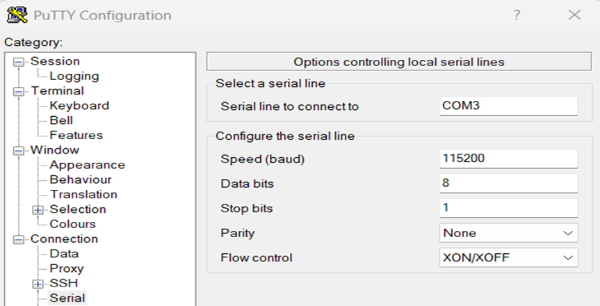
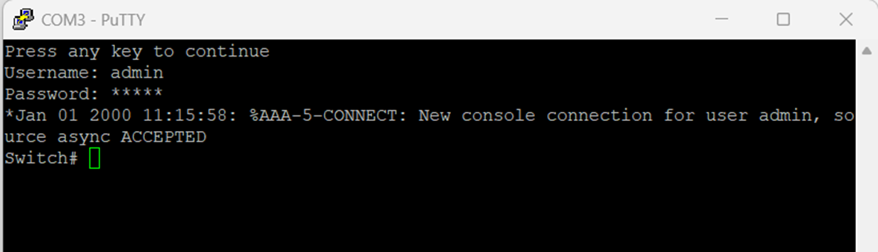
- Connect to the switch. Upon successful connection, you will see the device's console menu or command line interface.
2. IP Address Connection
By default, the Navijin GE6010-24P2S-L2 switch has two working IP addresses:
- Primary IP address: 192.168.1.1
- Secondary IP address: 192.168.0.1
- Subnet mask: 255.255.255.0
Steps:
- Connect your computer to one of the switch's Ethernet ports using a network cable.
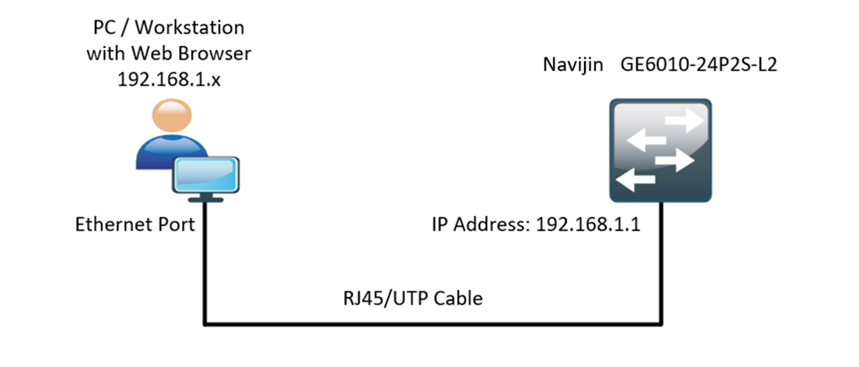
- Configure your computer's network adapter with an IP address in one of the following subnets:
- For the 192.168.1.1 IP address, set your computer's IP address to: 192.168.1.2
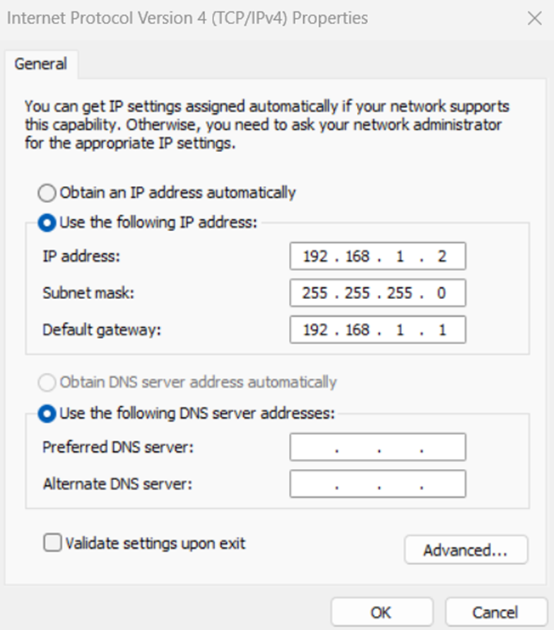
- For the 192.168.0.1 IP address, set your computer's IP address to: 192.168.0.2
- Subnet mask in both cases: 255.255.255.0
- Open your web browser and enter one of the following addresses:
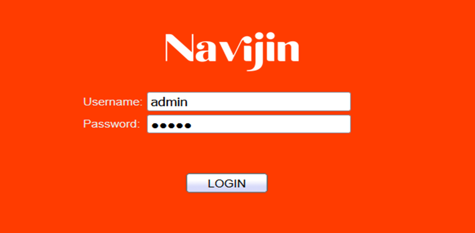
- When the authentication window appears, enter the following default credentials:
- Username: admin
- Password: admin
How to Configure the Management and SSH on Navijin L2/L3 Switches?
Full Configuration for Management and SSH on Navijin L2/L3 Switches
1. Access to the Management Interface
By default, the switch has an IP address of 192.168.1.1/24 in VLAN 1.
For the initial connection:
- Set the network interface of your computer to the same subnet (192.168.1.x, subnet mask 255.255.255.0).
- Connect to the switch through the console port.
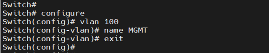
2. Creating VLAN 100 for Management
Enter configuration mode and create the new VLAN:
3. Assigning a Port for Management
Select the physical port through which management will be done (for example, GigabitEthernet 23):

After this, access via 192.168.1.1 will be disabled, and management will only be available through 192.168.100.100.
5. Configuring SSH for Secure Management
Enable SSH and set it to use version 2:
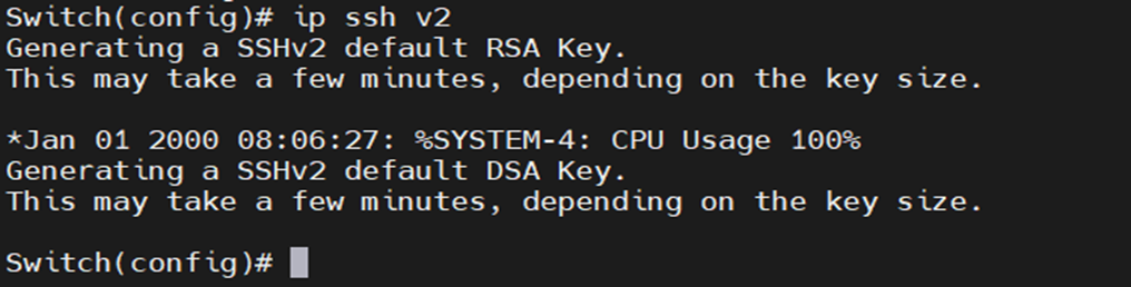
The system will automatically generate RSA and DSA keys for SSH.
After generating the keys, activate SSH:

The switch will now accept SSH connections.
Configuring Management and SSH via Web Interface on Navijin GE-6010-24P2S-L2
1. Access the Web Interface
By default, the switch has an IP address of 192.168.1.1/24 in VLAN 1.
To access the web interface for initial configuration:
- Set the network interface of your computer to the same subnet (192.168.1.x, subnet mask 255.255.255.0).
- Open a web browser and type the default IP address of the switch (192.168.1.1) in the address bar.
- Log in using the default username and password (usually admin/admin).
2. Create VLAN 100 for Management
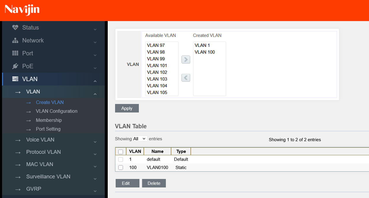
Once logged in, follow these steps to create VLAN 100:
- Navigate to the VLAN section from the main menu.
- Go to the Create sub-section.
- In the Available VLANs column, find VLAN 100 and move it to the Create VLAN column.
- Click the Apply button.
- After applying, VLAN 100 will appear in the VLAN Table on the same page.
3. Assign a Name to VLAN 100
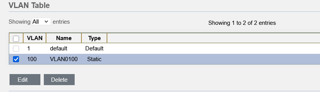
To assign a name to VLAN 100:
- In the VLAN Table, check the box next to VLAN 100.
- Click the Edit button.
- Enter the name MGMT for the VLAN.
- Click Apply to save the changes.

4. Assign VLAN 100 to Port 23
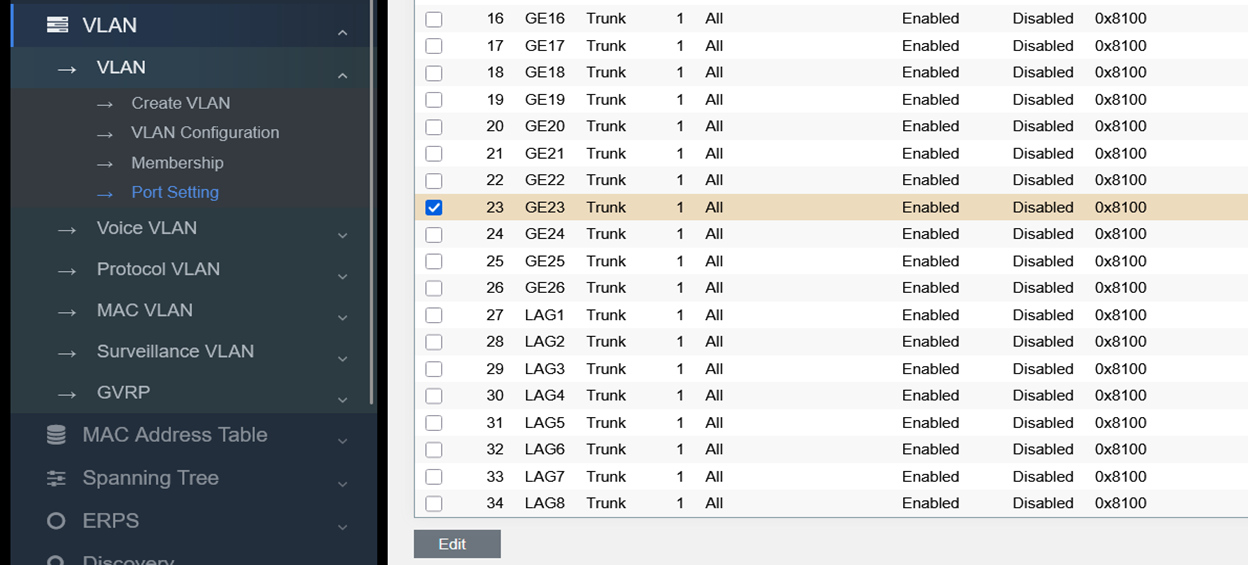
To assign VLAN 100 to port 23:
- Navigate to the VLAN section, then go to the Port Settings sub-section.
- In the Port Settings list, find Port 23 and check the box next to it.
- Click the Edit button.
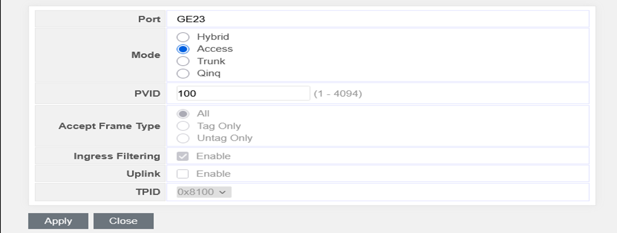
- In the opened window, select Access mode for the port.
- Change the PVID from 1 to 100.
- Click Apply to save the configuration.
5. Assign the Switch IP Address and Set Management VLAN
To assign a new IP address for management:
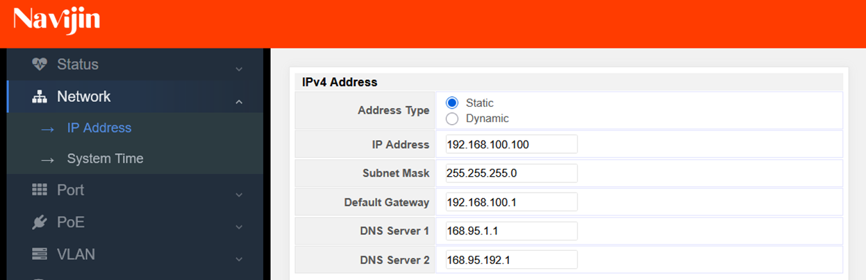
- Navigate to the Network section, then go to the IP Address sub-section.
- In the IPv4 Address window, select Address Type: Static.
- Enter the IP address 192.168.100.100, subnet mask 255.255.255.0, and default gateway 192.168.100.1.
- Scroll down and click Apply to save the settings.
- On your computer or laptop, change the IP to 192.168.100.2, subnet mask 255.255.255.0.
- Access the switch using the new IP 192.168.100.100.
6. Set the Management VLAN
To assign VLAN 100 as the management VLAN:
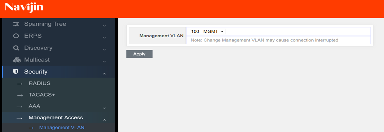
- Navigate to the Security section and go to the Management Access sub-section.
- Then, go to the Management VLAN sub-section.
- In the opened window, change the default VLAN from 1 to 100 (MGMT).
- Click Apply to save the changes.
- You will lose connection to the switch after this step.
7. Reconnect to the Switch
Since you have configured VLAN 100 for management, to reconnect:
- Connect your computer or laptop to Port 23 on the switch.
- On your computer, change the IP address to 192.168.100.2 with the subnet mask 255.255.255.0.
- Use the new IP address 192.168.100.100 to access the switch's web interface.
Now your switch operates in VLAN 100, and you can manage it via the web interface at 192.168.100.100. 🚀
8. Enable SSH for Secure Management
To enable SSH for secure management:
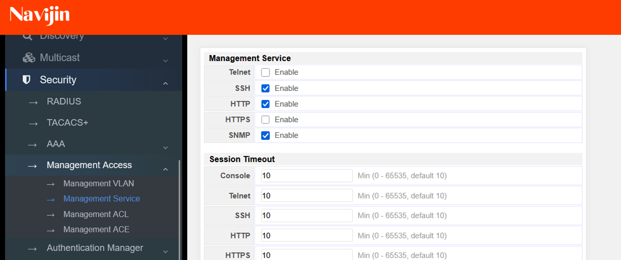
- Navigate to the Security section in the web interface.
- Go to the Management Access sub-section.
- Then, go to the Management Service sub-section.
- In the opened window, find SSH and check the box next to it.
- At the bottom of the page, click Apply to enable the SSH service.
How to Create a VLAN on Navijin L2/L3 Switches?
Working with VLAN on Navijin GE6010-24P2S-L2 Switch
1. Introduction to VLAN
VLAN (Virtual Local Area Network) is a method of segmenting a physical network into multiple logical networks. VLANs improve security, manageability, and network performance by isolating groups of devices.
2. Creating a VLAN (Web Interface)
1. Log in to the switch web interface.
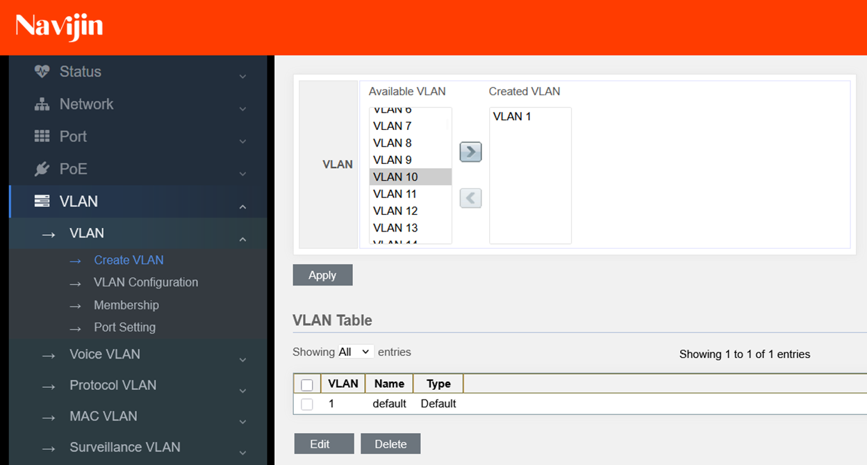
2. Go to VLAN → Create VLAN.
3. In the new window, you’ll see two columns:
- Available VLAN — VLANs available to create;
- Created VLAN — VLANs that are already created.
4. By default, all ports are in VLAN 1.
5. To create VLAN 10:
- Find VLAN 10 in the Available VLAN column;
- Move it to the Created VLAN column;
- Click Apply.
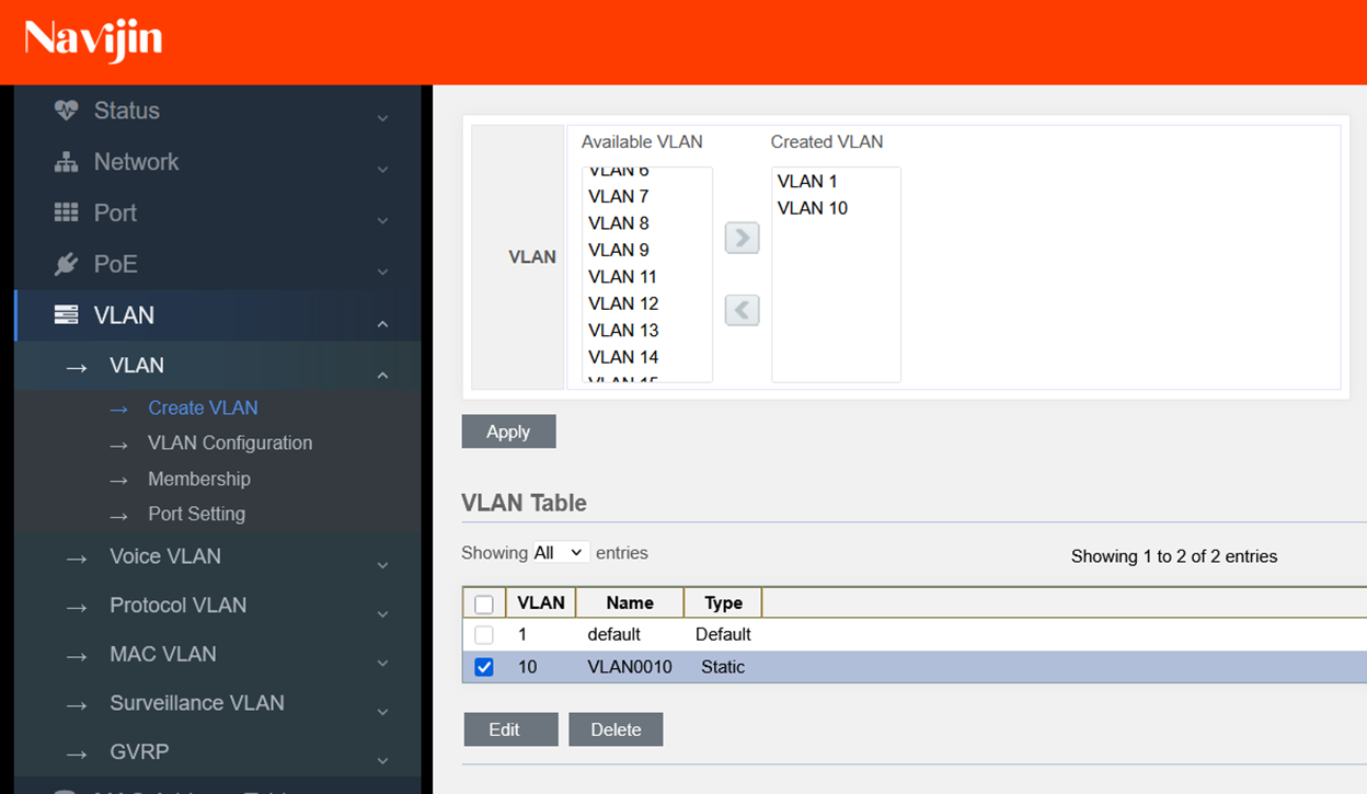
6. In the VLAN Table, VLAN 10 will now be listed.
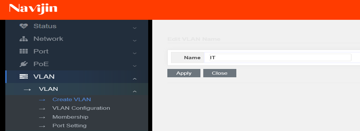
7. To assign a name to VLAN 10:
- Select VLAN 10;
- Click Edit;
- Enter a name, e.g., IT, and save.
3. Assigning a VLAN to a Port (Access Mode)
- Go to VLAN → Port Setting.
- Find the desired port, for example GE5, and click Edit.
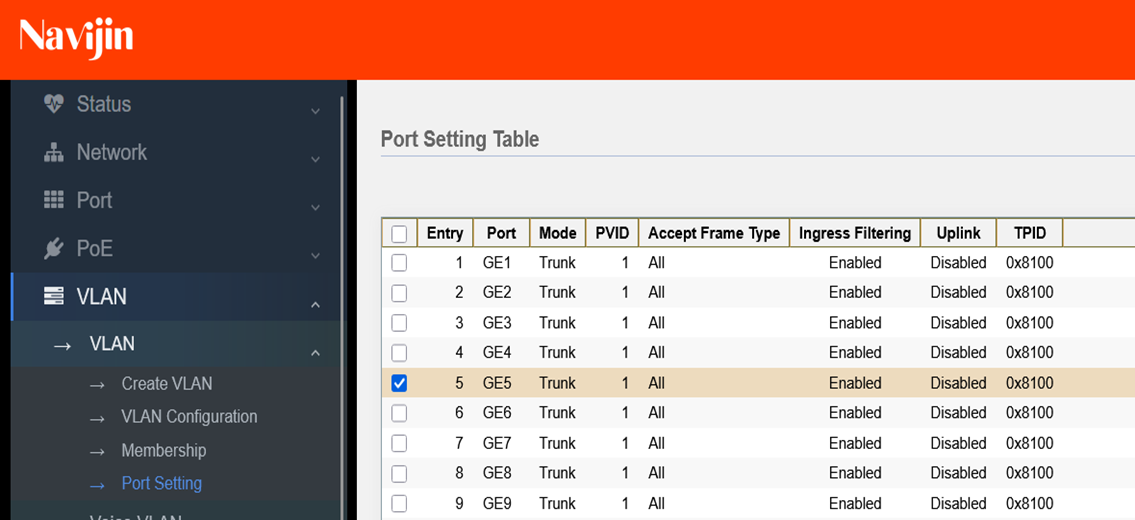
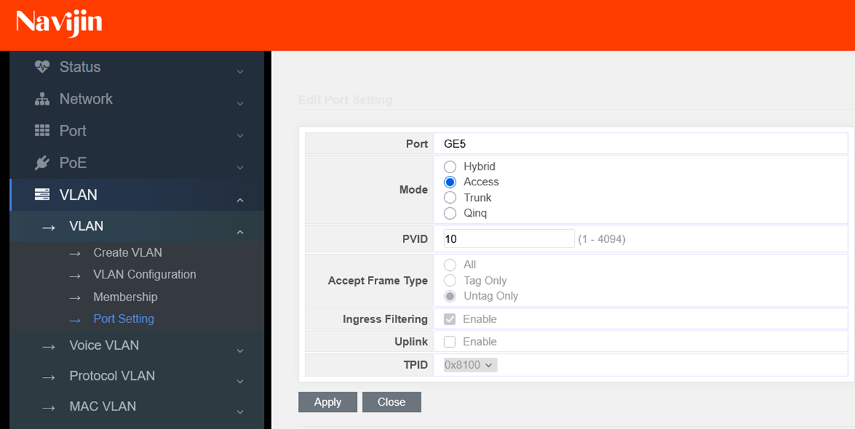
- In the window that opens:
- Set Mode to Access;
- In the PVID field, enter 10 instead of 1.
- Click Apply.
- Now port GE5 is assigned to VLAN 10.
4. Setting Up a Trunk Port
By default, all ports on the Navijin GE6010-24P2S-L2 switch are in trunk mode. To allow VLAN 10 on a trunk port:
- Go to VLAN → Membership.
- Find port GE24 and click Edit.
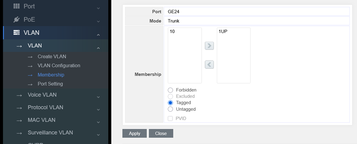
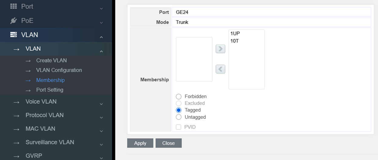
3. In the new window:
- Find VLAN 10 in the left column;
- Move it to the right column (allowed VLANs for this port).
4. Click Apply.
5. VLAN 10 is now allowed on trunk port GE24.
Working with VLAN on Navijin GE6010-24P2S-L2 (CLI)
1. Creating a VLAN and Naming “IT”
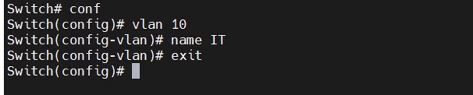 \
This creates VLAN 10 with the name “IT”.
2. Assigning VLAN 10 to Port GE5 (Access Mode)
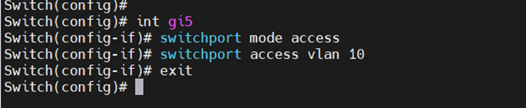
Port GE5 is now in Access mode and assigned to VLAN 10.
3. Configuring Trunk Port GE24

Port GE24 is configured as a Trunk port and now allows VLAN 10.
IP Telephony
How to Initial Connection and Access to the Management Interface?
Step 1. Initial Connection and Access to the Management Interface
For the initial setup of the IP-PBX Navijin VPX80-4O12S, a direct connection to the device is required.
· Connect the network port of your PC to the LAN port of the PBX using a patch cord.
· By default, a DHCP server is enabled on the PBX side. Your PC's network adapter will automatically obtain an IP address from the default management subnet (192.168.100.0/24). Manual static IP configuration on the PC is not required.
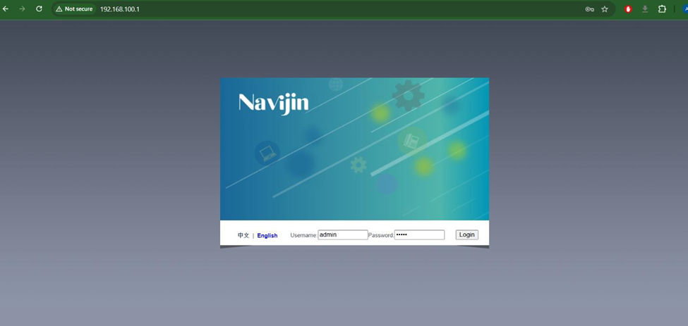
· Open a web browser and navigate to the default gateway IP address: 192.168.100.1.
· On the Navijin welcome page, select your preferred interface language (English) and enter the administrator credentials. The default is Username: admin, Password: admin.
· Click the Login button.
Step 2. Administrator Password Change (Modify Password)
Immediately after the first successful login, the system will prompt you to change the factory password for security reasons.
· In the Old Password field, enter the current password (admin).
· Specify the new password in the New Password and Confirm Password fields.
· Click the Modify button to apply the new settings.
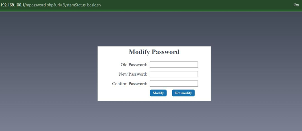
Practical recommendation: If the basic configuration is being performed within an isolated laboratory environment or test bench, this step can be skipped by clicking the Not modify button. In this case, the default password will continue to be used for login. When
deploying the PBX into full (production) operation, changing the password is mandatory.
Step 3. Creating a User Account (Extension) for the IP Phone
After logging into the system, you must create an internal subscriber profile to which the IP phone will subsequently connect.
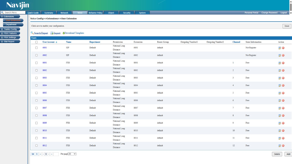
· In the main top navigation menu, go to the Voice tab.
· In the left side menu, expand the Extensions section and select the User Extension submenu. A table listing all current internal extensions will open in the workspace. Typically, default numbers are already displayed there: SIP accounts (e.g., 6001, 6002) and FXS ports (8001–8012).
· To register a new IP phone, scroll to the very bottom of the page and click the Add button in the lower right corner.
Step 4. Basic Subscriber Parameters (Basic Settings)
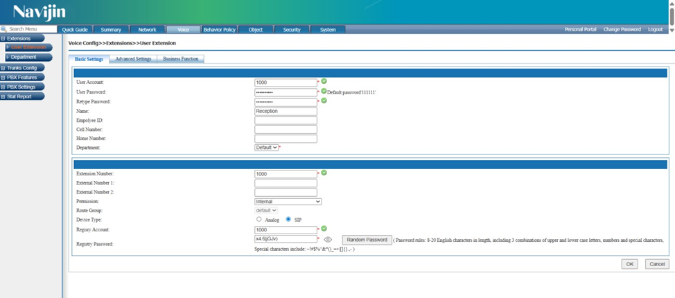
In the newly opened subscriber creation window, on the Basic Settings tab, you need to fill in two main blocks: user account parameters and SIP registration settings.
Block 1. User Account (Top part of the window)
· User Account: Enter the desired internal number, for example, 1000.
· User Password / Retype Password: Set a password for the user to access the personal PBX portal (by default, 111111 is often used).
· Name: Specify the subscriber's name or zone name (e.g., Reception), which will be displayed during internal calls.
Block 2. Number and Registration Settings (Bottom part of the window)
· Extension Number: Specify the same number — 1000.
· Permission: Select the access level for calls (e.g., Internal — internal calls only, without external outbound access).
· Device Type: Be sure to switch the selector to SIP, as we are configuring an IP phone, not an analog device (Analog).
· Registry Account: By default, it matches the number (1000). This login will be used in the IP phone settings.
· Registry Password: Set a password for SIP registration. It is recommended to click the Random Password button to generate a complex and secure password (e.g., x4.E[CJv)).
Important: Be sure to copy and save the Registry Account and Registry Password. They will be required at the final stage when configuring the IP phone itself.
After filling in this data, do not click the OK button. Proceed to the next tab — Advanced Settings at the top of the window.
Step 5. Advanced Subscriber Settings (Advanced Settings)
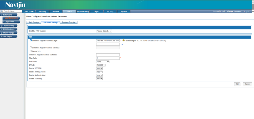
To ensure security, it is necessary to restrict the IP addresses from which registration of this SIP account is allowed.
· Without closing the subscriber creation window, go to the top Advanced Settings tab.
· In the SIP section, check the Permitted Registry Address Range checkbox.
· In the activated field, enter the address of your trusted local subnet and mask. In our case, this is the subnet issued by the PBX DHCP server: 192.168.100.0/255.255.255.0.
Part 2. Configuring the Navijin VIP-T70PGN IP Phone
Step 6. Connecting and Logging into the IP Phone Web Interface
Since the DHCP server is enabled by default on the PBX interface, the IP phone automatically receives network settings when connected to the same local network.
· Find out the network address assigned to the IP phone. To do this, after the device
boots up, press the OK button on its front panel. In our example, the phone received the address 192.168.100.4.
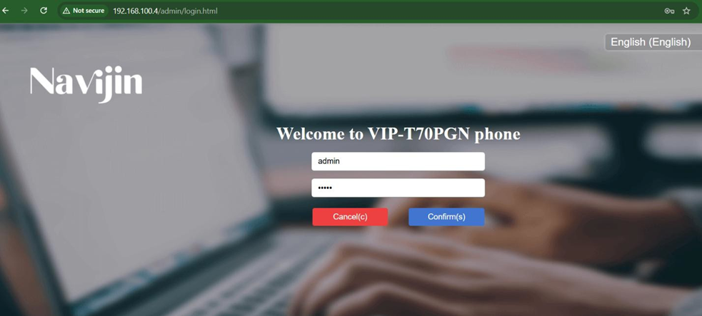
· Open a web browser on your PC and enter this IP address in the address bar: http://192.168.100.4.
· On the VIP-T70PGN welcome page, enter the factory administrator credentials:
o Login: admin
o Password: admin
· Click the Confirm(s) button to enter the control panel.
Step 7. SIP Account Registration on the Phone
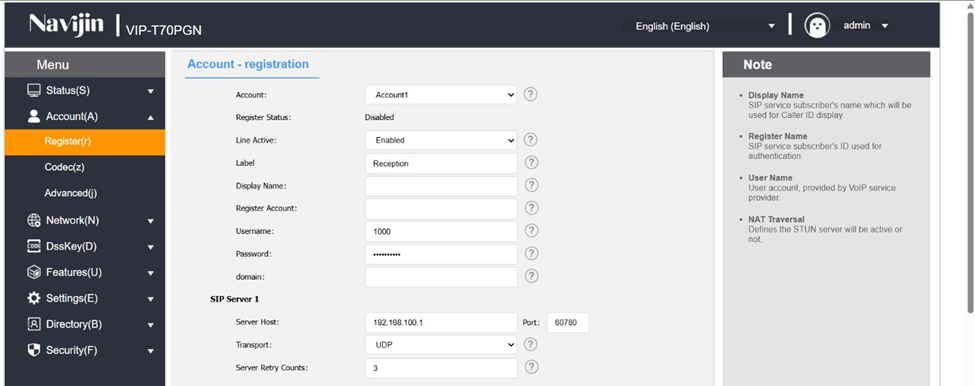
This is a crucial stage where we link the physical device with the account created on the PBX.
· In the left navigation menu, go to the Account section and select the Register submenu.
· Select the active line (for example, Account 1) and set the following parameters:
o Line Active: Switch to the Enabled state.
o Username: Specify the internal number — 1000.
o Password: Enter the SIP registration password (Registry Password) that we obtained on the PBX side.
· In the SIP Server 1 block, fill in the server details:
o Server Host: Specify the IP address of your PBX — 192.168.100.1.
o Port: Attention! Be sure to change the default value from 5060 to 60780. This is strictly essential for correct interaction with this PBX model.
· Click the Confirm button at the bottom of the page.
Step 8. Registration Status Verification
After saving the settings, the system initiates the process of exchanging SIP packets.
· Check the Register Status field in the phone's web interface. Upon successful connection, the status will change to Registered (highlighted in green).
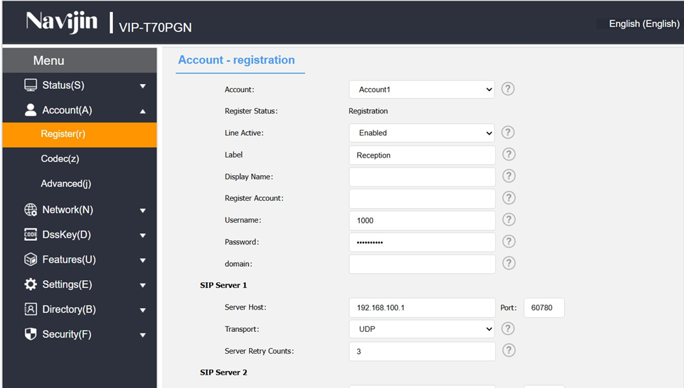
· On the LCD of the Navijin VIP-T70PGN device itself, the number 1000 should appear in the upper corner without any error icons.
Wireless Infrastructure
How to Initially Configure Navijin Wireless Access Point and Gateway?
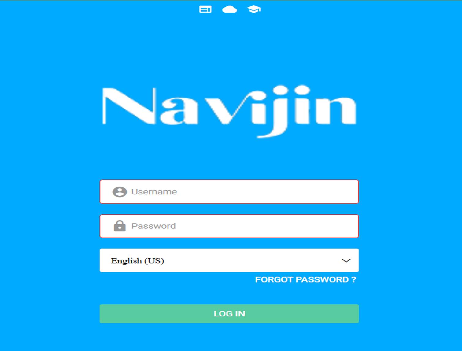
Login Page - Navijin NG-GE108-P
• Access the web interface by entering the default IP address 192.168.11.1 in your browser.
• The PC receives an IP from the same subnet automatically.
• Login credentials: admin / admin.
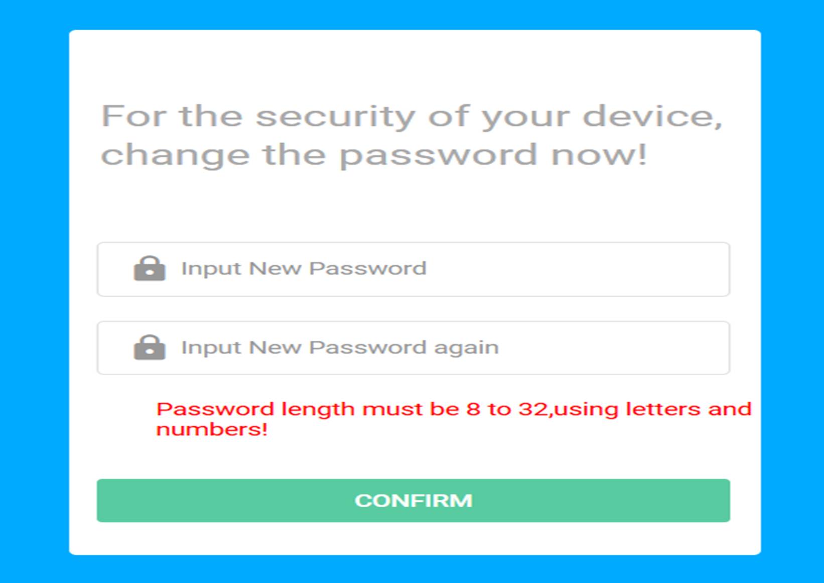
Change Default Password
• Upon first login, the system prompts you to change the default password for security purposes.
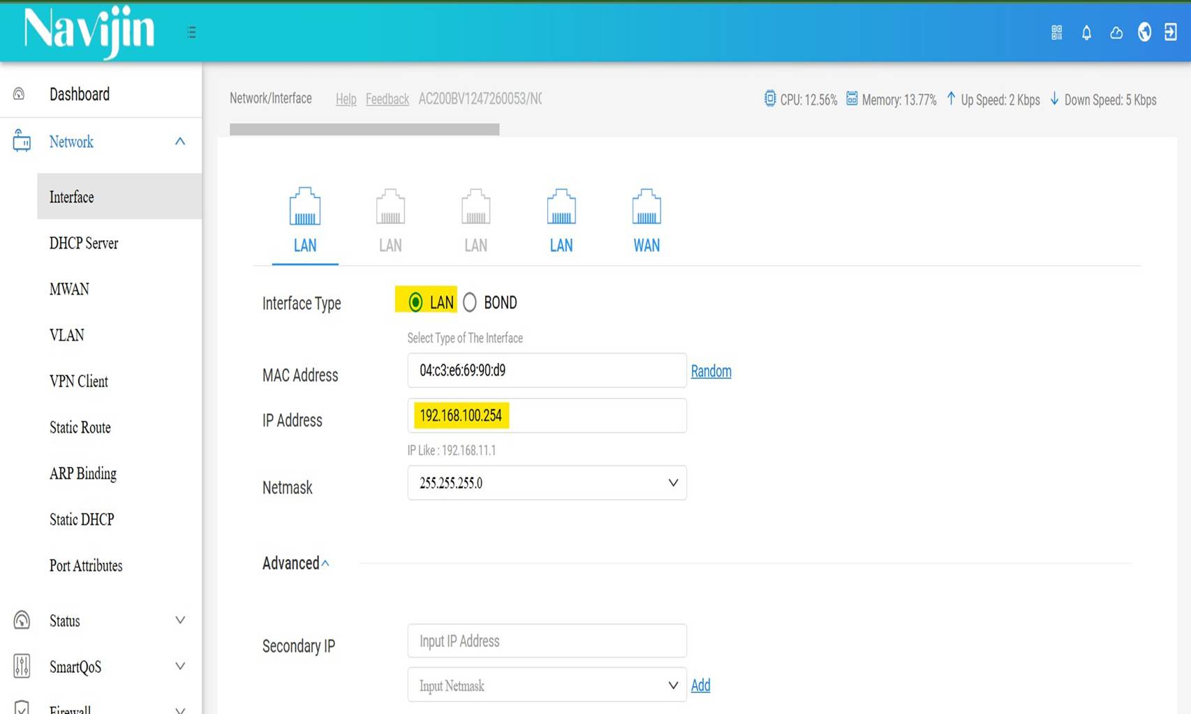
Interface Configuration
• Go to Network > Interface.
• By default, all ports are in BOND mode.
• To assign VLANs, change the port to LAN, then set the IP address and subnet mask.
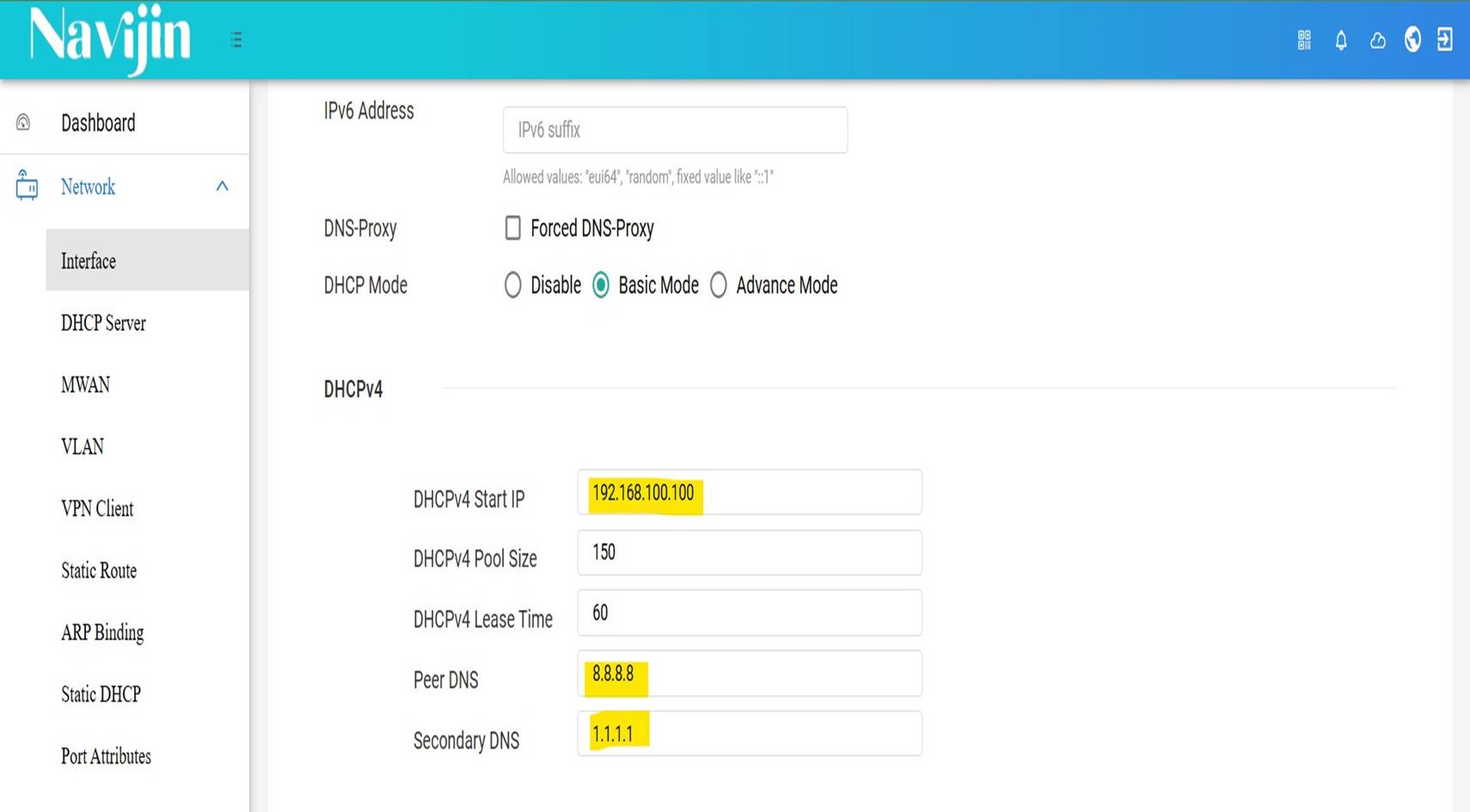
DHCP Configuration for Interface
• In the Advanced section of the interface settings, enable and configure the DHCP server.
Creating a VLAN
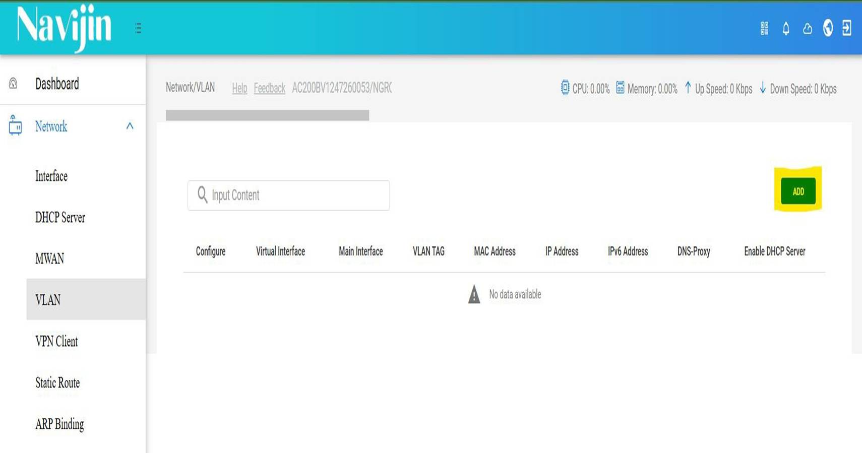
• Navigate to Network > VLAN, click ADD.
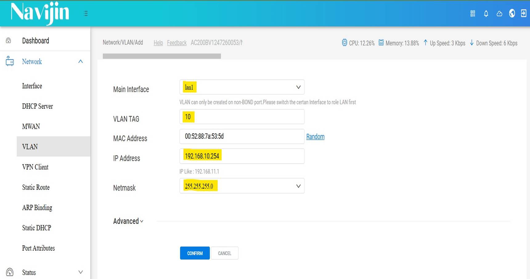
• Select the interface, assign a VLAN ID, IP address, and subnet mask.
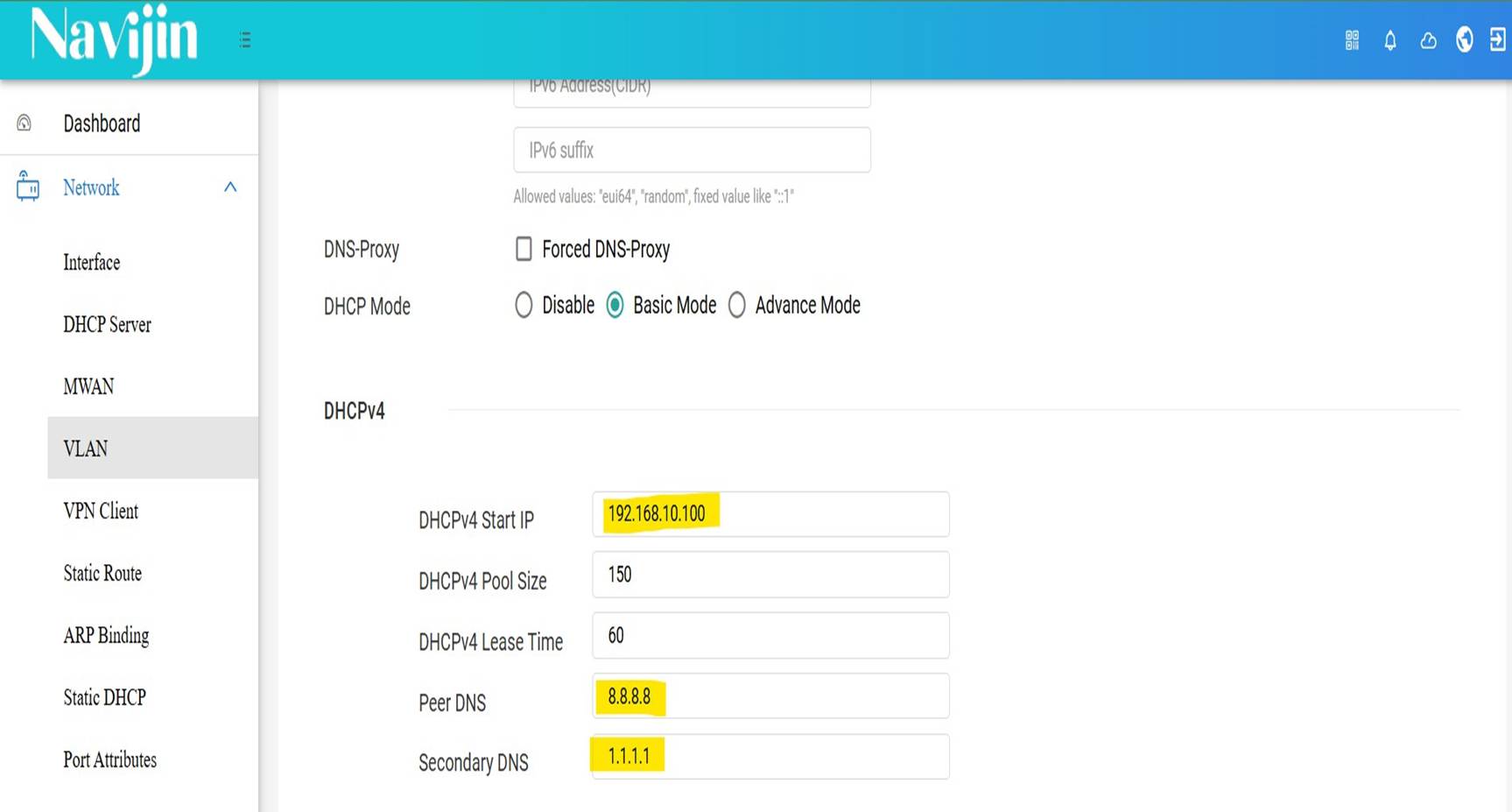
• In the Advanced section, enable the DHCP server for this VLAN.
VLAN Overview
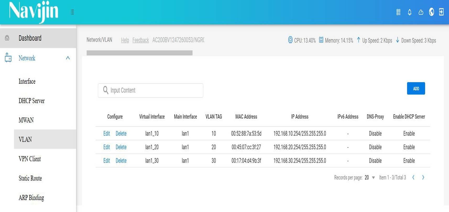
• After creating VLANs, go to Network > VLAN to view the list of all configured VLANs.
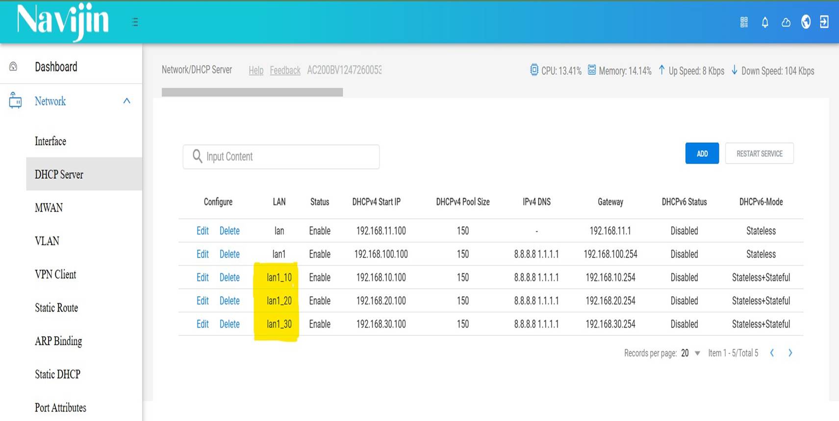
DHCP Server Overview
• Go to Network > DHCP Server to view and manage DHCP servers for each interface or VLAN.
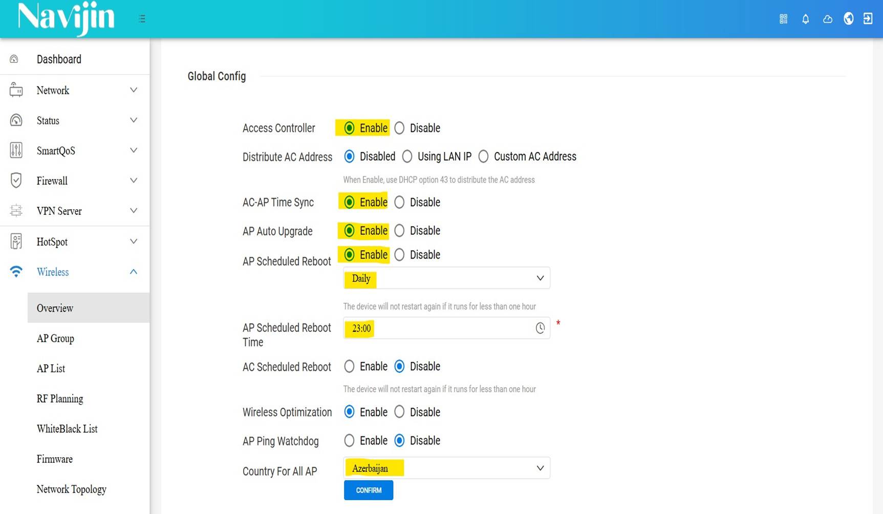
Wireless Controller Settings
• Go to Wireless > Overview and enable the following options:
• - Access Controller: activates AP management
• - AC-AP Time Sync: syncs time across access points
• - AP Auto Upgrade: enables auto firmware upgrade
• - AP Scheduled Reboot: schedule automatic reboots
• - Country For All AP: set your country
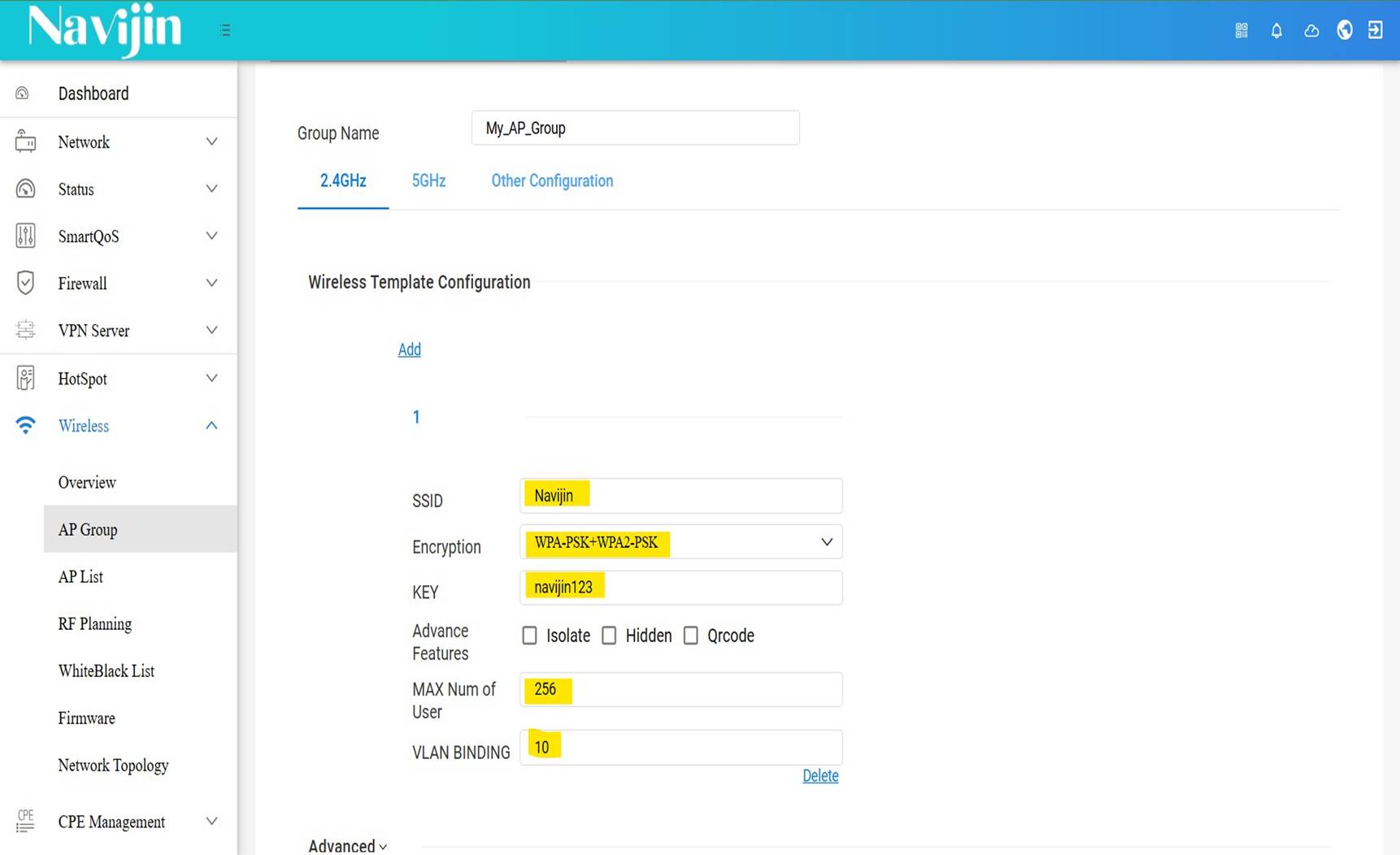
Creating AP Group – 2.4GHz Settings
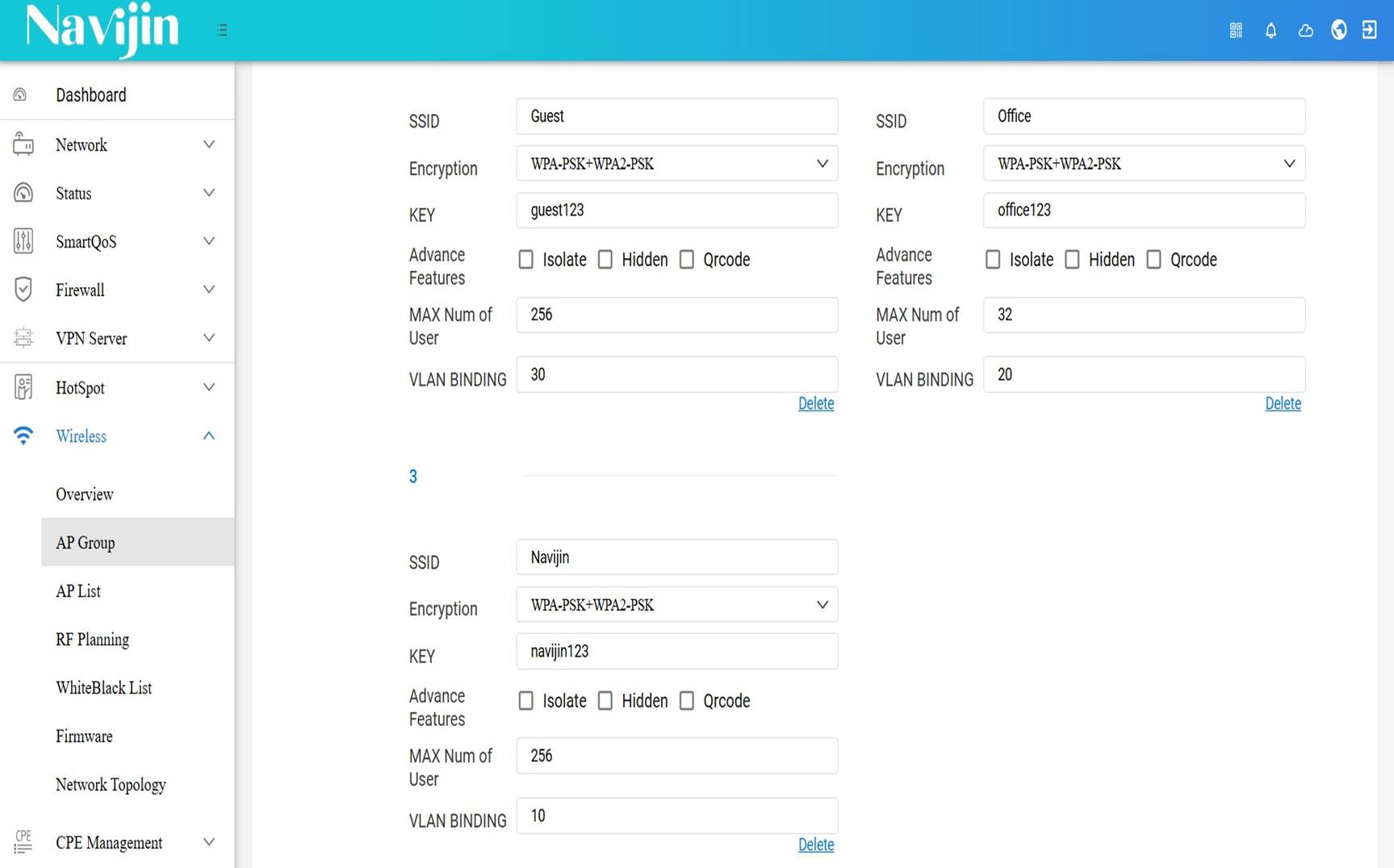
• Go to Wireless > AP Group, create a group (e.g. My_AP_Group).
• Under 2.4GHz, configure:
• - SSID
• - Encryption
• - Key
• - Max Number of Users
• - VLAN Binding
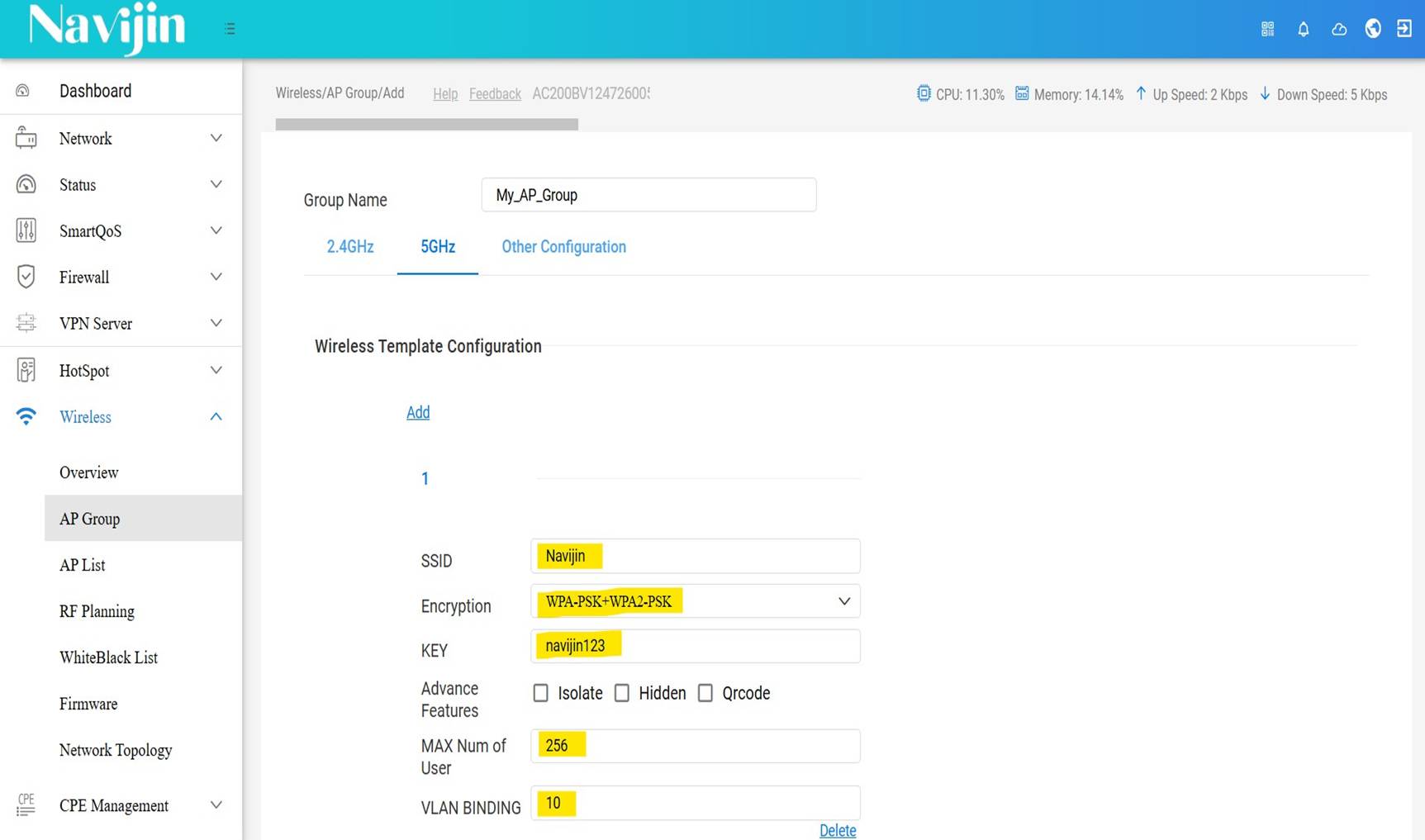
Creating AP Group – 5GHz Settings
• In the same AP group, under 5GHz, configure SSID, encryption, key, max users, and VLAN binding.
Binding AP to a Group
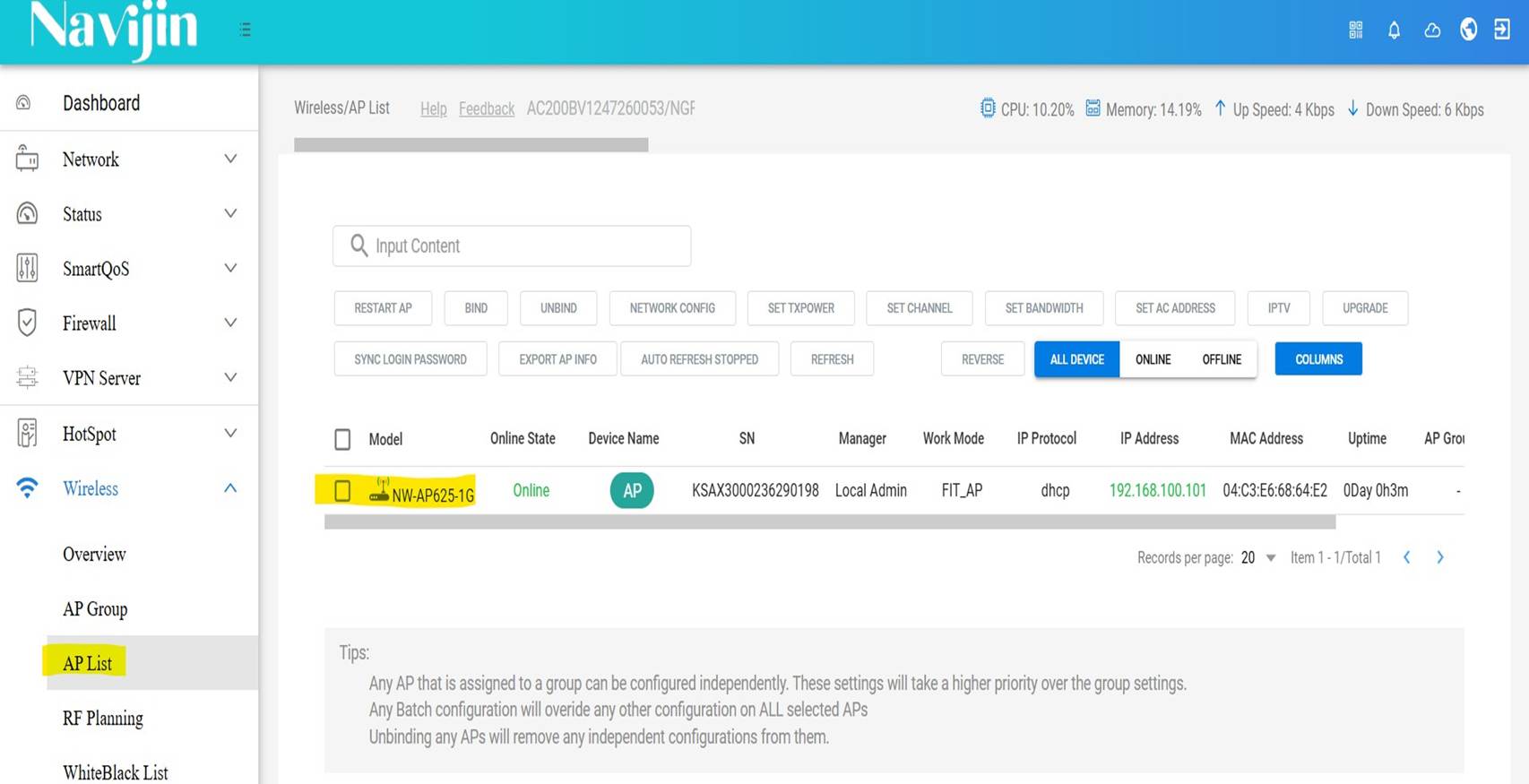
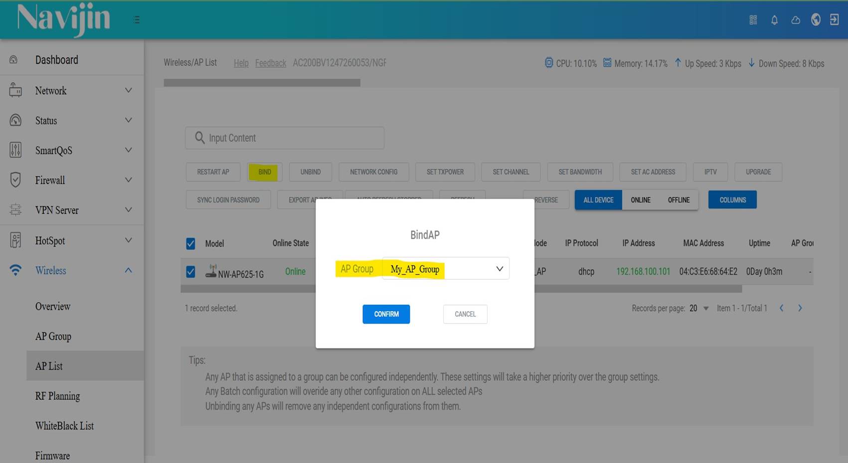
• Select the desired access point and click BIND.
• In the pop-up window, select your previously created group (My_AP_Group).
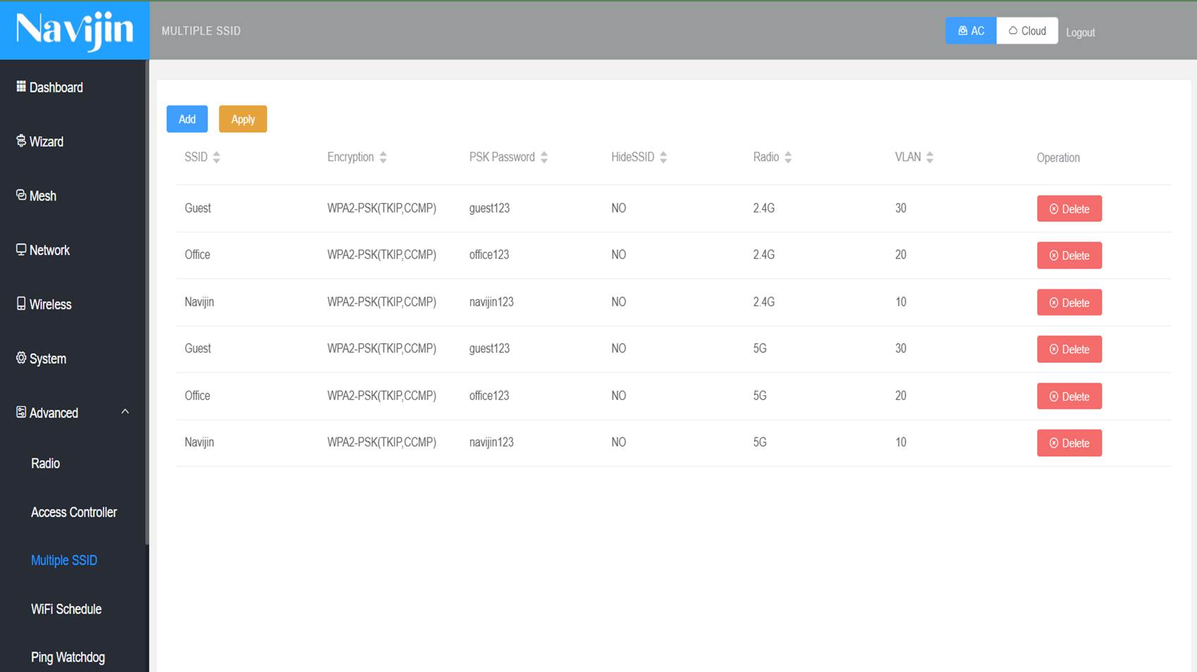
AP Group Configuration Applied
• After binding, the access point will automatically apply the group configuration.
Checking Connected Clients
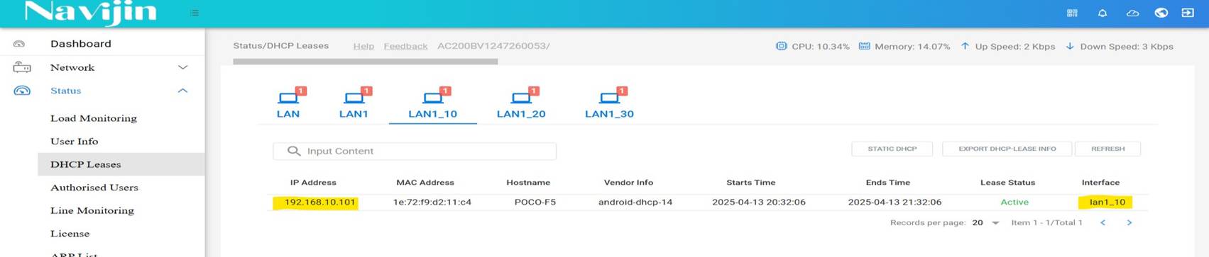
• Go to Status > DHCP Leases to verify that connected devices receive IP addresses and are assigned to the correct VLANs based on their SSID.
Still have questions?
Can not find what you are looking for? Our support team is here to help you.
Contact Support